close
Choose Your Site
Global
Social Media
Views: 0 Author: Site Editor Publish Time: 2025-09-24 Origin: Site
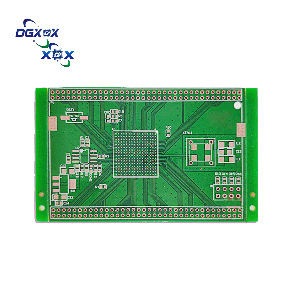
PCBs power nearly every device we use daily. A PCB circuit board connects and supports electronic parts, shaping product performance. Different types exist to meet unique needs, from simple gadgets to advanced medical tools. In this article, you'll explore the latest 2025 trends and learn how industries like automotive, aerospace, and consumer electronics benefit.
A PCB circuit board can be as simple as a single copper layer. In a single-sided design, all conductive traces are etched on one side, while components sit on the opposite face. This structure makes it easy to produce and keeps design straightforward.
Single-sided PCBs are valued for their low manufacturing costs and fast production cycles. However, they limit circuit complexity because paths cannot overlap, making them unsuitable for advanced electronics. They are best when performance demands are basic and reliability outweighs design flexibility.
Single-sided PCBs appear in consumer products like calculators, printers, and radios. They also support LED lighting systems where efficiency and cost are critical. In power supplies, they manage simple current distribution without needing multi-layer routing. These boards fit well where durability and affordability matter more than density.
A double-sided PCB circuit board has conductive copper layers on both sides of the substrate. Components can be mounted on both surfaces, and vias connect traces through drilled holes. This allows designers to increase density and improve circuit performance without moving to multi-layer boards.
This design is a step up in complexity compared to single-sided boards. It supports more connections and delivers stronger electrical performance. However, fabrication requires additional steps and costs more than single-sided types. Still, the added versatility makes them popular in higher-value applications.
Double-sided PCBs serve industries that require compact but capable circuits. In automotive electronics, they power dashboard displays and control modules. Industrial control systems rely on them for reliable performance in machinery and automation. Amplifiers—both audio and RF—use them for cleaner signals and reduced noise.
A multi-layer PCB circuit board stacks three or more copper layers with insulating material between them. Each layer is carefully laminated under heat and pressure to create a compact unit. Designers use vias—plated through, blind, or buried—to connect signals across these layers. This structure allows engineers to route complex circuits while keeping the board small.
Multi-layer PCBs offer several key benefits over single- and double-sided boards:
● High circuit density: They support thousands of connections in limited space.
● Improved performance: Shorter signal paths reduce interference and noise.
● Space savings: Compact design enables smaller devices without losing function.
The versatility of multi-layer PCBs makes them indispensable in advanced industries:
● Computers: Used in motherboards, GPUs, and data storage systems.
● Telecommunications: Found in routers, base stations, and network switches.
● Medical Imaging: Enable precision in MRI, CT, and ultrasound equipment.
● Aerospace: Critical in avionics systems where weight and reliability matter.
While powerful, multi-layer boards bring unique hurdles. Their complex structure increases manufacturing time and cost. Repair is also challenging, as faults may lie within inner layers. Specialized fabrication equipment and strict quality checks are essential. For high-reliability sectors, these challenges are justified by superior performance.
Feature | Multi-Layer PCB | Single/Double-Sided PCB |
Layer Count | 3–100+ | 1–2 |
Circuit Density | Very High | Low to Medium |
Performance | High Speed, Low Noise | Basic to Moderate |
Applications | Computers, Telecom, Medical | Lighting, Power Supplies |
Cost | Higher | Lower |
A rigid PCB circuit board is built on a solid substrate such as FR-4 fiberglass. This strong base gives stability and prevents bending. Designers prefer it when they need circuits that remain fixed. Rigid boards are also easier to test and repair since components are clearly placed and pathways are visible.
These boards provide reliable performance in everyday electronics. They appear in laptops, desktop computers, and automotive engine control units. Their cost is usually lower compared to flexible options, making them suitable for high-volume production.
Flexible PCBs are made from polyimide or other bendable plastics. Their lightweight and space-saving design allows them to fit in devices where rigid boards cannot. Engineers can fold, twist, or curve them without breaking the circuit paths.
They are used in wearables like smartwatches and fitness trackers. Cameras, foldable phones, and compact medical devices also rely on them. Though more expensive, they cut down on weight and assembly space, which is valuable in modern miniaturized products.
A rigid-flex PCB circuit board combines both rigid and flexible layers. The flexible sections connect rigid areas, creating a hybrid that is both durable and adaptable. This design reduces the need for connectors, lowering assembly weight and potential failure points.
They are widely adopted in aerospace and defense systems where vibration resistance and reliability are vital. In healthcare, pacemakers and imaging tools depend on them for compact yet strong circuitry. Smartphones and tablets also benefit from this design, where space-saving and durability are key.
PCB Type | Substrate Material | Key Strengths | Common Uses |
Rigid | FR-4 fiberglass | Stability, easy repair | Laptops, automotive ECUs |
Flexible | Polyimide/plastic | Lightweight, bendable | Wearables, cameras, foldables |
Rigid-Flex | Hybrid mix | Durable, space-saving | Aerospace, pacemakers, smartphones |
Note: Rigid-flex boards often reduce part count and improve reliability in high-stress environments.
A high-frequency PCB circuit board is engineered for signals above 500 MHz and often over 2 GHz. It uses materials with low dielectric constant (Dk) and low loss tangent (Df). These properties ensure faster signal transmission and reduce distortion. Common materials include PTFE composites and specialized laminates that outperform standard FR-4 in high-speed applications.
The boards are also designed to handle strict electrical tolerances. Even small variations in material can affect performance. For this reason, manufacturers use advanced testing to confirm stability before mass production.
High-frequency PCBs are essential in fields where speed and clarity are critical:
● Telecommunications: Used in antennas, base stations, and 5G network gear.
● Radar Systems: Military and automotive radar rely on them for accurate detection.
● Medical Imaging: Found in MRI, ultrasound, and advanced diagnostic devices.
● Satellite Communication: Ensures reliable long-distance signal transfer.
These applications demand precision, and high-frequency PCBs provide the stability required for mission-critical equipment.
Designers must consider several factors when working with high-frequency PCBs:
● Heat resistance: Materials must withstand continuous operation under high loads.
● Low water absorption: Moisture can change dielectric properties, reducing performance.
● Precise fabrication: Tight control over trace width and spacing is required.
● Cost impact: Specialized materials and processes make them more expensive than standard boards.
Ignoring these details can lead to poor signal quality and higher failure rates. Proper material selection and reliable suppliers are essential for consistent results.
Property | High-Frequency PCB | Standard PCB (FR-4) |
Frequency Range | 500 MHz–2 GHz+ | < 500 MHz |
Dielectric Constant (Dk) | Low, stable | Higher, less stable |
Loss Tangent (Df) | Very low | Moderate |
Typical Applications | Telecom, radar, imaging | Consumer devices |
Cost Level | High | Low to medium |

High-power electronics often generate large amounts of heat. If not managed, this heat can shorten component lifespan and reduce efficiency. A standard PCB circuit board may not handle thermal stress well, leading to performance issues. This is why thermal management is critical in industries such as automotive, telecom, and LED lighting. Boards with enhanced thermal conductivity help maintain stable operation and protect sensitive circuits.
Aluminum-backed PCBs, also called metal-core PCBs, are designed with a metal base layer. Aluminum is most common, but copper is also used for higher thermal conductivity. The metal base allows heat to spread quickly across the board, preventing hot spots.
These PCBs are also more rigid compared to standard boards. Their mechanical strength makes them suitable for demanding environments. In addition, they provide low thermal expansion, which protects solder joints from cracking under temperature changes.
Aluminum-backed PCBs are widely adopted where both heat control and durability are essential:
● LED Lighting: Ensures long lifespan by preventing overheating of diodes.
● Automotive Power Modules: Handles high currents in engine control and electric vehicle systems.
● Power Supplies: Supports stable operation under heavy loads.
● Consumer Electronics: Used in devices needing compact, high-power circuits.
Their ability to combine rigidity and heat dissipation makes them indispensable in both consumer and industrial designs.
PCB Type | Base Material | Key Strengths | Typical Applications |
Standard FR-4 PCB | Fiberglass | Cost-effective, versatile | Consumer electronics, general use |
Aluminum-Backed PCB | Aluminum/Copper | Heat dissipation, rigidity | LED lighting, automotive, power supplies |
Metal-Core PCB | Metal alloys | High thermal conductivity | Industrial and high-power systems |
An HDI PCB circuit board uses microvias, blind vias, and buried vias to increase circuit density. This allows more connections in less space, which is critical for today’s compact devices. By stacking layers tightly, HDI boards enable high-speed signal transmission while keeping designs lightweight.
Their use is widespread in smartphones, tablets, and portable medical devices. The combination of small size and high performance makes them a top choice in modern consumer electronics. However, they demand precise fabrication, often raising production costs compared to standard boards.
Heavy copper PCBs feature thicker copper layers, often above 3 oz per square foot. This design supports higher current loads and better heat distribution. They are widely used in motor drives, power converters, and industrial systems where reliability is non-negotiable.
High-Tg PCBs use substrates with a higher glass transition temperature. They withstand elevated thermal stress without deforming. This makes them ideal for automotive electronics, industrial controls, and harsh manufacturing environments. Both types expand the range of applications where PCBs can function reliably under extreme conditions.
Ceramic-based PCBs stand out for their superior thermal conductivity and dielectric properties. They are more stable under high heat compared to FR-4 or even metal-core boards. This strength makes them suitable for aerospace, RF communication, and advanced military systems.
Although costly, ceramic PCBs ensure high reliability in mission-critical systems. Their ability to manage both power and high-frequency signals positions them as a strategic solution in specialized industries.
PCB Type | Key Properties | Common Applications |
HDI PCB | Microvias, high density | Smartphones, tablets, wearables |
Heavy Copper PCB | Thick copper, high current load | Motor controls, power systems |
High-Tg PCB | Heat-resistant substrates | Automotive, industrial controls |
Ceramic PCB | Thermal stability, low loss | Aerospace, RF, military |
Selecting the right PCB circuit board depends on project needs. Start by evaluating the number of layers, substrate material, and whether flexibility is required. Rigid boards suit stable environments, while flexible boards fit compact designs.
Cost is another factor. Single-sided and double-sided PCBs are more affordable, while multi-layer and ceramic boards are higher-priced but deliver superior performance. Consider the environment too—heat, vibration, and space constraints can influence durability and reliability.
IPC sets standards that help define PCB quality and reliability:
● Class 1: Basic function, suitable for toys and simple electronics.
● Class 2: Reliable operation for devices like laptops and consumer gadgets.
● Class 3: Mission-critical quality for aerospace, military, and medical devices.
These classifications help align board performance with end-use expectations. Choosing the correct class prevents over-engineering while ensuring reliability where it matters.
When planning a PCB, match its type with device performance requirements and budget. A low-cost board may save money but fail under stress, while an over-specified board can waste resources. Involving PCB manufacturers early can help validate design feasibility and material availability.
Clear documentation also speeds up production and reduces errors. Always review your bill of materials, trace widths, and surface finishes before ordering. Prototype testing is essential to confirm real-world performance.
Selection Factor | Considerations | Impact on Application |
Layers | Single, double, multi-layer | Circuit complexity, density |
Materials | FR-4, polyimide, ceramic, aluminum | Heat resistance, flexibility |
Flexibility | Rigid, flexible, rigid-flex | Space use, durability |
Cost | Varies by type and layer count | Budget alignment |
Environment | Heat, vibration, moisture | Reliability under stress |
IPC Class | 1, 2, or 3 | Defines expected quality level |
Different PCB circuit board types offer unique strengths, from single-sided for simple devices to multi-layer, flexible, and high-frequency options for advanced systems. Comparing features, costs, and applications helps businesses select the most efficient solution. Careful evaluation ensures performance, reliability, and budget alignment. Dongguan Xinrongxing Technology provides high-quality PCB solutions with strong thermal control and durability, delivering real value across industries.
A: A PCB circuit board connects components, and different types exist to meet varied performance and design needs.
A: Compare layers, materials, and flexibility of the PCB circuit board with your budget and environmental demands.
A: A metal-core PCB circuit board with aluminum backing offers excellent thermal management for power supplies and LEDs.
A: A multi-layer PCB circuit board allows high density, improved performance, and space-saving design for computers and telecoms.
A: Yes, a flexible PCB circuit board costs more but saves space and weight, ideal for wearables and foldable devices.


